You've measured your space, chosen the perfect strip, and planned the layout. Now comes the moment of truth: cutting the strip to size and connecting it to power—or joining two sections together.
A poor connection is the number one cause of flickering, dim sections, and complete failure. The good news? With the right techniques, you can create connections that are as reliable as the strip itself. This guide covers everything from basic cutting to professional-grade soldering.
Part 1: Where and How to Cut
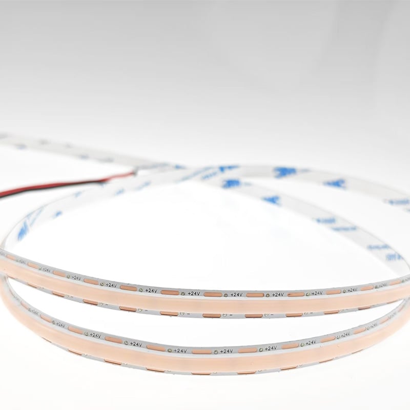
LED strips are designed with cut marks—small copper pads or scissors icons printed on the PCB. These marks indicate where the circuit can be safely severed.
The Golden Rule: Only cut along the designated cut lines. Cutting anywhere else breaks the circuit and destroys that section.
How to cut:
· Use a sharp pair of scissors or a craft knife.
· Cut precisely through the middle of the copper pads.
· Ensure the cut is straight—angled cuts can expose too much copper or damage adjacent pads.
What if you need a non‑standard length? Most strips are divided into segments (e.g., every 5cm or 10cm). You can only cut at segment boundaries. Check your strip's datasheet for the cutting interval.
Part 2: Connecting Without Soldering (Connectors)
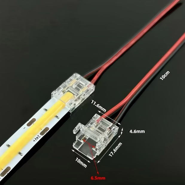
For quick, tool‑free connections, snap‑on or screw‑type connectors are popular. They come in various styles:
· Strip‑to‑wire connectors – Attach wires to the end of a cut strip.
· Strip‑to‑strip connectors – Join two strip ends in a straight line.
· L‑shaped / corner connectors – Turn 90° without bending.
· T‑shaped connectors – Split power to multiple branches.
Step‑by‑step using snap‑on connectors:
1. Open the connector's hinged lid.
2. Slide the cut end of the strip into the slot, ensuring the copper pads align with the metal prongs.
3. Close the lid firmly until it clicks.
4. Gently tug the strip to confirm it's secure.
Pros: Fast, no heat, reusable.
Cons: Less durable than soldering; prone to loosening over time; not suitable for high‑current or outdoor applications.
Pro tip: For permanent installations, consider using screw‑terminal connectors—they clamp down on the copper with screws, providing a more secure mechanical grip.
Part 3: The Gold Standard – Soldering
Soldering creates a permanent, low‑resistance connection that outlasts any connector. It's essential for long runs, high‑power strips, or outdoor installations.
Tools you'll need:
· Soldering iron (25–40W with a fine tip)
· Lead‑free solder (60/40 or 63/37 tin‑lead also works)
· Flux (optional but helpful)
· Heat‑shrink tubing (to insulate each joint)
· Wire strippers
· Helping hands or a clamp to hold the strip
Step‑by‑step soldering:
1. Prepare the strip – Gently scrape the copper pads with a knife or fine sandpaper to remove oxidation. This ensures good solder adhesion.
2. Tin the pads – Heat the pad with the soldering iron and apply a small amount of solder. The pad should be covered with a thin layer of shiny solder. Repeat for both positive (+) and negative (−) pads.
3. Tin the wires – Strip about 5mm of insulation from your connecting wires. Twist the strands, then apply solder to coat the exposed copper.
4. Join them – Place the tinned wire on the tinned pad. Apply heat with the iron until both melt together, then remove the iron. Hold still for a few seconds until the solder solidifies.
5. Insulate – Slide a piece of heat‑shrink tubing over the joint before soldering (if you forgot, you'll need to redo it). After soldering, slide the tubing over the joint and apply heat with a heat gun or lighter until it shrinks snugly.
6. Repeat for both positive and negative connections – Ensure they don't touch each other (use separate heat‑shrink tubes).
Pro tip: Work on a non‑flammable surface. The strip's adhesive can melt if overheated—keep the iron on the pad for no more than 2–3 seconds at a time.
Part 4: Handling Corners and Angles
Corners are tricky because strips don't bend sharply. Here are your options:
· Use a pre‑made corner connector – Plug the strip ends into an L‑shaped connector. Quick but may protrude.
· Solder a 90° turn – Cut the strip at the corner, solder wires between the two ends, and fold the wires to create the angle. This gives a clean, flush result.
· Bend the strip gently – COB strips are flexible enough to curve around a radius of ~20mm. For SMD, avoid sharp bends—they can crack the PCB.
· Use an aluminium profile corner – Some profiles come with pre‑formed corner pieces that hide the transition completely.
Part 5: Common Connection Mistakes
Mistake Consequence Fix
Cutting off‑mark Entire segment fails Measure twice, cut once; use correct cut points
Reversing polarity (+ and −) Strip doesn't light, may damage LEDs Mark polarity on both strip and wires with tape
Cold solder joint (dull, grainy) Intermittent connection, flickering Re‑heat and add more solder until shiny
Too much solder Bridges adjacent pads, causing short Use desoldering braid to remove excess
No heat‑shrink Bare wires can short against surfaces Always insulate each joint
Using under‑sized wires Overheating, voltage drop Use 18 AWG or thicker for long runs
Part 6: When to Use Connectors vs. Soldering
Situation Recommended
Temporary installation or test setup Connectors
Under‑cabinet lighting (hidden, low stress) Either – connectors are fine
Long runs 5 metres Soldering (lower resistance)
Outdoor or damp locations Soldering + waterproof heat‑shrink
High‑power strips ( 15W/m) Soldering only
Quick repairs on site Connectors (if you have spares)
Part 7: Pro Tips for Perfect Connections
· Pre‑tin everything – Tinning both the pad and the wire before joining makes soldering faster and reduces heat exposure.
· Use flux – A tiny dab of flux on the pad helps solder flow evenly and prevents oxidation.
· Label your wires – Use red for positive, black for negative to avoid polarity mistakes.
· Test after each connection – Connect power after every joint, not just at the end. This isolates problems immediately.
· Keep the strip flat – While soldering, support the strip on a flat surface to prevent movement.
Final Thoughts
Mastering cutting and connecting techniques transforms LED installations from frustrating to satisfying. Whether you choose snap‑on connectors for speed or soldering for permanence, the key is precision and care.
A reliable connection ensures consistent brightness, longer lifespan, and safety. It's worth investing a few extra minutes to do it right.
Need connectors, soldering kits, or pre‑soldered jump leads? We stock everything you need—including waterproof heat‑shrink and high‑quality screw‑terminal connectors. Shop our accessories range and get professional results every time.
 Hot News
2026-07-24
2026-07-24
2026-07-24
2026-07-24
2026-07-24
2026-07-24
 EN
EN