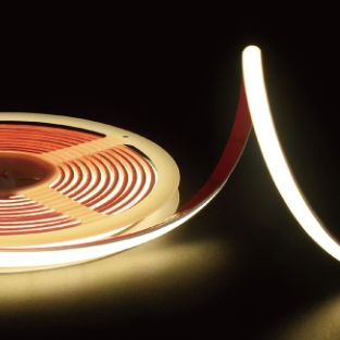
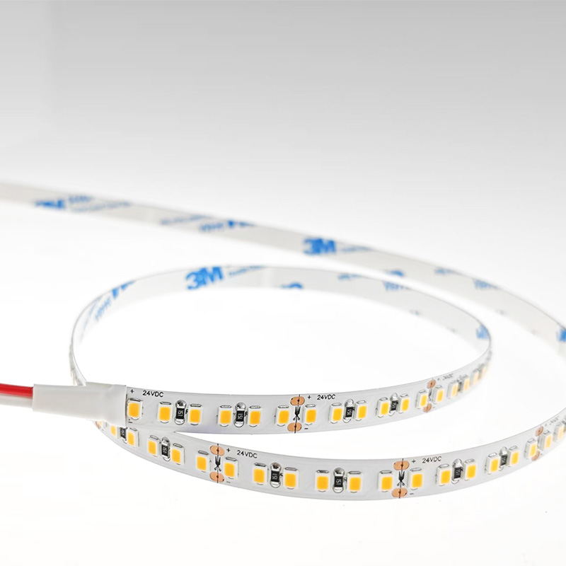
Installing LED strip lighting in commercial or large-scale residential projects requires more than just peeling and sticking. Professional engineers and installers follow structured protocols to ensure reliability, safety, and longevity. Here's a practical engineering perspective on LED strip installation.
1. Pre-Installation Planning
Load Calculation
· Calculate total wattage: W/m × total length × 1.2 (safety margin)
· Determine if multiple drivers are needed for long runs
· Plan for power injection points every 5–8 metres
Voltage Drop Analysis
· For 24V systems: limit runs to 10 metres without injection
· For 12V systems: limit runs to 5 metres
· Use voltage drop calculators to verify cable sizing
· Consider 24V over 12V for any run exceeding 5 metres
Thermal Assessment
· Calculate expected heat output: approximately 20–30% of input power becomes heat
· Determine if aluminium profiles are required (typically 10W/m)
· Assess ambient temperature conditions
2. Material Selection
Choose the Correct Strip Grade
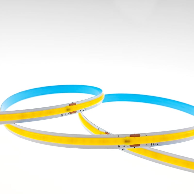
· Residential: CRI 80–90, standard SMD or COB
· Commercial: CRI 90+, 2oz copper, ≤ 3 SDCM
· Industrial: IP65+, impact-resistant, high lumen output
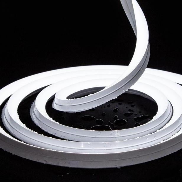
· Exterior/Exposed: UV-resistant silicone, IP67+, robust profile
Driver Selection Criteria
· Enclosed vs. ventilated: drivers lose 10–15% efficiency without airflow
· Power Factor: ≥ 0.9 for commercial installations
· Operating temperature range: -20°C to +50°C minimum
· Dimming compatibility: PWM frequency 2000Hz for flicker-free operation
3. Mechanical Installation
Surface Preparation
· Clean with isopropyl alcohol (70%+)
· Allow 2–3 minutes drying time
· For critical installations: apply 3M Primer 94 or equivalent
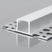
Profile Mounting
· Use screws for profiles 1 metre length (adhesive alone is insufficient)
· Allow 2–3mm expansion gaps between profile lengths
· Ensure profiles are straight with a spirit level
Strip Insertion
· Peel only the first 30–50cm of release liner at a time
· Apply firm, even pressure using a rubber roller
· Avoid stretching the strip during application
Cutting and Connection
· Cut only at designated copper pad marks
· For each connection: tin wires, solder, and cover with heat-shrink tubing
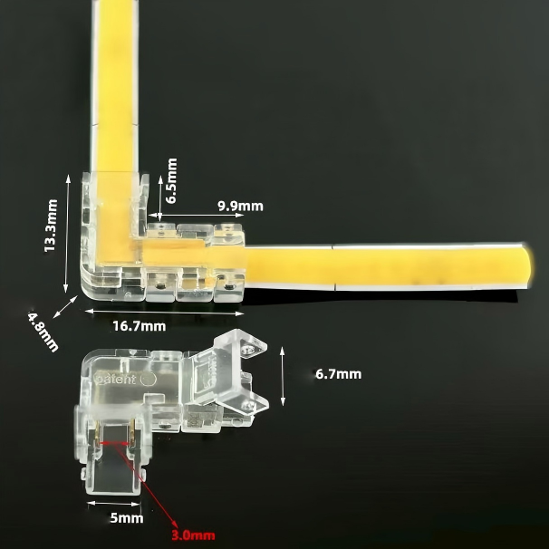
· For field connections: use gel-filled waterproof connectors
4. Electrical Installation
Wire Sizing
Distance (Driver to Strip) Current (Amps) Minimum AWG
< 2m < 5A 20
< 2m 5–10A 18
2–5m < 3A 20
2–5m 3–5A 18
2–5m 5–8A 16
5–10m < 3A 18
5–10m 3–5A 16
5–10m 5–8A 14
Wiring Topology
· Use parallel wiring for multiple strip sections
· Avoid daisy-chaining beyond 3 metres total length
· For long runs: use a distribution block with individual fused outputs
Grounding and Safety
· Ground the power supply housing
· Use Class 2 or SELV-rated drivers
· Install GFCI for outdoor installations
· Consider surge protection for commercial projects
5. Commissioning and Testing
Pre-Power Checks
· Verify all connections match polarity (+ to +, – to –)
· Confirm voltage matches strip specification (12V or 24V)
· Check for any exposed copper or shorts
Power-On Sequence
· Power on at low brightness first
· Gradually increase to full brightness
· Monitor for flicker, colour shifts, or uneven output
· Measure current draw at the driver – compare with calculations
Performance Testing
· Measure voltage at the far end of each run
· Check for voltage drop exceeding 5%
· Verify colour consistency between different reels
· Test dimming response across 0–100% range
Burn-In Test
· Run at full power for 24–48 hours
· Monitor for premature failures
· Check for any colour shifts or flickering
6. Documentation and Handover
As-Installed Documentation
· Mark all power injection points
· Record driver model, wattage, and voltage
· Document dimming and control settings
· Provide emergency contact details for technical support
For Maintenance Logs
· Record installation date and batch numbers
· Log warranty start dates for all components
· Schedule future inspection intervals
7. Common Engineering Pitfalls
Pitfall Engineering Solution
Under-specifying wire gauge Always size for peak current, not average
Using PVC cable in outdoor runs Use LSZH (Low Smoke Zero Halogen) or weatherproof
No thermal management for drivers Ensure 50mm clearance around all drivers
Hardwiring without a disconnect Use a plug-in connection for serviceability
Neglecting earth bonding Always ground driver enclosures
No spare capacity in the driver Leave 20% margin for future expansion
8. Final Checklist
· Load calculation performed (with 20% margin)
· Voltage drop analysis completed
· Driver and strip specifications matched
· All surfaces cleaned and prepared
· Mechanical fasteners used (not just adhesive)
· Wiring gauge selected per current requirements
· Parallel wiring used for multiple sections
· Full system tested on bench before installation
· Burn-in test completed (24–48 hours)
· As-installed documentation prepared
Final Thoughts
Engineering-grade LED installation is systematic and deliberate. By following these protocols, installers can deliver lighting systems that perform reliably for their full rated lifetime, reducing callbacks, warranty claims, and client dissatisfaction.
Need technical specifications or engineering support for your project? Our team of LED specialists offers design consultations, system verification, and installation guidance for commercial and residential projects worldwide. Contact us with your project requirements.
 Hot News
2026-07-24
2026-07-24
2026-07-24
2026-07-24
2026-07-24
2026-07-24
 EN
EN